Gear Calculator & Involute Gear SVG/DXF/STL Generator
Module, pitch, centre distance, ratio — and export gears as SVG, DXF or STL · free, no signup
Download the gears
See Gear Calculator & Involute Gear SVG/DXF/STL Generator in action
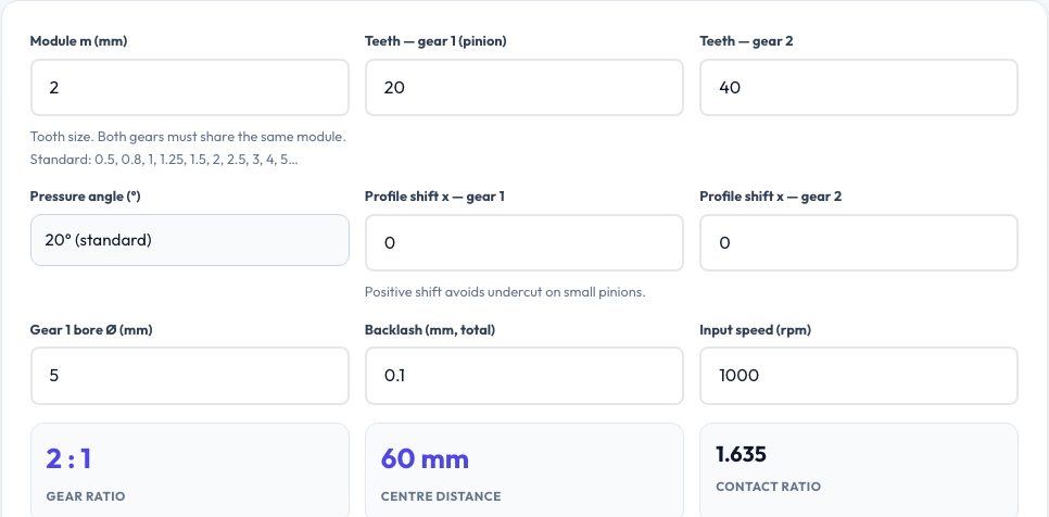
Free Spur Gear Calculator and Involute Gear Generator
Enter a module, tooth counts for two gears, a pressure angle and optional profile shift and backlash, and this tool computes the full spur-gear data: pitch, base, tip and root diameters, addendum and dedendum, whole depth, tooth thickness, circular pitch, centre distance, gear ratio, contact ratio and output speed. It warns about undercut on small tooth counts and about a low contact ratio, the two classic design mistakes.
The same numbers drive a real involute gear generator. The tooth flank is calculated from the involute of the base circle, with proper root and tip arcs, and rotated into a complete gear outline. Download either gear — or the meshing pair at the correct centre distance — as an SVG or DXF (true millimetres, with a bore circle) for laser cutting and CNC, or as an STL solid with the face width you choose for 3D printing. A live preview shows the two gears meshed.
Key features
Complete gear data
Diameters, depths, thickness, centre distance, ratio and contact ratio.
True involute profile
Flank from the base circle with tip and root arcs; profile shift and backlash supported.
SVG, DXF and STL
Laser/CNC outlines at 1:1 and a 3D-printable solid.
Meshing preview
See both gears in mesh at the right centre distance.
How to use it
- Enter module and the tooth counts of both gears.
- Adjust pressure angle, profile shift and backlash if needed.
- Check ratio, centre distance and warnings.
- Download SVG, DXF or STL of each gear or the pair.
Worked example
Example
Module 2, 20 and 40 teeth, 20° pressure angle: pitch diameters 40 and 80 mm, tip diameters 44 and 84, root diameters 35 and 75, centre distance 60 mm, ratio 2:1, contact ratio 1.64. At 1000 rpm in, 500 rpm out.
Who uses this tool
Mechanical engineering students
Check gear calculations and see the geometry.
Laser-cutter and CNC users
Get accurate gear outlines for plywood or acrylic gears.
3D-printing makers
Print gears with the right centre distance.
Tips for the best results
- Both gears must share the same module and pressure angle.
- Use at least 17 teeth (20°) or apply positive profile shift to avoid undercut.
- Add 0.1–0.2 mm of backlash for laser-cut or printed gears.
- For printed gears use thicker face widths and a slightly looser centre distance.
Common mistakes to avoid
- Mixing modules between gears.
- Ignoring the minimum tooth count and ending up with undercut.
- Cutting laser gears at nominal centre distance without allowing for kerf.
Why use AZRS QuickFix?
It is 100% free, needs no signup and has no watermark or usage limits. The tool runs in your browser, so what you type stays on your device, and it works on phones, tablets and desktops. New tools are added every week — bookmark this page or browse the full QuickFix toolbox.
Frequently asked questions
What is module?
Pitch diameter ÷ number of teeth, in millimetres — the standard measure of tooth size.
Is the profile a true involute?
Yes — computed from the base circle involute equation.
What about helical or bevel gears?
Only spur gears are generated.
Is the STL printable?
Yes — it is an extruded closed solid with a bore hole.