Thread & Fastener Chart — Tap Drill, Clearance, Counterbore
Metric & imperial thread data: tap drill, clearance holes, head sizes, torque · free, no signup
See Thread & Fastener Chart — Tap Drill, Clearance, Counterbore in action
Free Thread & Fastener Lookup — Metric and Imperial
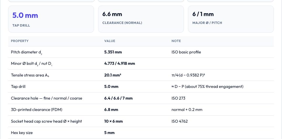
Every mechanical design needs the same handful of numbers over and over: the tap drill for a thread, the clearance hole for a bolt, the counterbore for a socket-head cap screw. This lookup gives them for metric threads M1.6 to M36 in coarse and fine pitch, with the minor and pitch diameters, the tensile stress area, the ISO 273 close/normal/loose clearance holes, ISO 4762 cap-screw head size and hex key, DIN 974 counterbore and depth, ISO 10642 countersunk head diameter and ISO 4032 nut size across flats.
Choose a property class (4.6, 8.8, 10.9, 12.9 or A2-70) and it estimates the preload at 70% of proof load and a tightening torque with the textbook K = 0.2 nut factor. A second tab lists the imperial UNC/UNF sizes from #2-56 to 1-8 with major diameter, TPI, pitch and the tap drill and clearance drill. For 3D-printed holes, add 0.2 mm to the normal clearance size.
Key features
Metric M1.6–M36
Coarse and fine pitches with pitch/minor diameters and stress area.
Hole sizes
Tap drill, ISO 273 clearance (fine/normal/loose) and 3D-printed clearance.
Head and nut data
Cap-screw head, hex key, counterbore, countersink and nut dimensions.
Imperial UNC/UNF
#2-56 to 1-8 with tap and clearance drills.
How to use it
- Choose a metric thread and pitch (or the imperial tab).
- Read the tap drill and clearance hole.
- Check head, counterbore and nut dimensions.
- Use the preload and torque guidance for the property class.
Worked example
Example
M5 coarse: pitch 0.8, tap drill 4.2 mm, normal clearance 5.5 mm (5.7 mm for 3D-printed holes), socket head 8.5 × 5 mm, 4 mm hex key, counterbore Ø10 × 5.4 mm, tensile stress area 14.2 mm², 8.8 preload ≈ 5.8 kN.
Who uses this tool
CAD students
Model holes and fasteners correctly the first time.
Machinists
Tap drill and clearance at a glance.
Makers and 3D printing users
Hole sizes that actually fit printed parts.
Tips for the best results
- Use normal clearance for general work and close for locating dowels.
- Counterbore depth should exceed the head height by ~0.4 mm for flush mounting.
- Lubricated threads need less torque than the dry values shown.
- For critical joints use a torque specification or a calculation, not a rule of thumb.
Common mistakes to avoid
- Using the nominal diameter as the tap drill.
- Using coarse clearance holes where alignment matters.
- Treating the torque figure as a guaranteed specification.
Why use AZRS QuickFix?
It is 100% free, needs no signup and has no watermark or usage limits. The tool runs in your browser, so what you type stays on your device, and it works on phones, tablets and desktops. New tools are added every week — bookmark this page or browse the full QuickFix toolbox.
Frequently asked questions
How is tap drill calculated?
Drill ≈ major diameter − pitch, which gives about 75% thread engagement.
Which standard for clearance holes?
ISO 273 close, medium and coarse series.
Are torque numbers exact?
No — they are a typical rule of thumb for dry steel threads (K = 0.2).
Does it include BSP/NPT?
Not currently — metric and unified (UNC/UNF) only.